DieselNet Technology Guide » Combustion in Diesel Engines » Diesel Spray Formation and Mixing
DieselNet | Copyright © ECOpoint Inc. | Revision 2026.09
This is a preview of the paper, limited to some initial content. Full access requires DieselNet subscription.
Please log in to view the complete version of this paper.
In-cylinder mixing enhancement upstream of the lift-off length can be achieved with smaller injection hole size and higher fuel injection pressure. However, these approaches present practical limits and alternative approaches to achieve this enhancement have been developed in the form of Ducted Fuel Injection (DFI) and the related Cooled Spray (CS) technology. Impressive soot reductions have been achieved with DFI that warrant a closer examination.
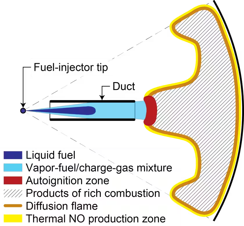
DFI is a means to enhance mixing upstream of the lift-off length, developed at Sandia National Laboratories. It involves placing a duct downstream of the injector nozzle holes but upstream of where flame lift-off occurs, Figure 1 [3606][3607][3608][3609][3610].
The primary benefit of the duct is through enhanced turbulent mixing upstream of the lift-off length (LOL) that yields a reduction in peak centerline fuel/air ratio at the LOL. A jet-pump effect at the duct inlet greatly enhances the amount of intake charge entrained into the jet close to the injector nozzle. However, the walls of the duct prevent further entrainment until after the duct outlet. Within the duct, the flow velocity is zero at the inner wall of the duct which increases the velocity gradients that drive turbulent mixing. This enhanced mixing as well as the boost in near-nozzle air entrainment leads to a reduction in the centerline equivalence ratio within and downstream of the duct. If the richest mixtures can be maintained at equivalence ratios of approximately two or lower in the autoignition zone, soot formation can be prevented (see the discussion of flame lift-off). The duct is also believed to limit over-mixing at the periphery of the spray to minimize over lean conditions. Cooler mixtures could also be present in the duct due to the use of cooler charge-gas from the thermal boundary at the chamber wall and because the duct itself might be cooler than the ambient in-cylinder gases. Video 1 and Figure 2 illustrate the lower soot formation potential of this approach.
(Courtesy of Sandia National Laboratories)
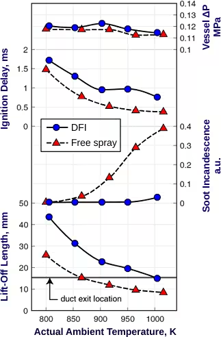
It should be noted that while there is a significant increase in the near-nozzle air entrainment with DFI, the total amount of air entrained into the jet upstream of the LOL does not necessarily increase. In some cases, it may be less than with a free jet. However, the centerline fuel/air ratio is significantly lower and is the primary reason for DFI’s lower soot emissions [6864].
###