(Courtesy of Heinz Heisler)
DieselNet | Copyright © ECOpoint Inc. | Revision 2026.06
This is a preview of the paper, limited to some initial content. Full access requires DieselNet subscription.
Please log in to view the complete version of this paper.
Internal combustion engines consisting of a piston reciprocating in a cylinder and connected by a connecting rod to a crankshaft—most commonly four-stroke diesel and spark-ignited engines—have become entrenched for many applications for at least a century. Yet, alternative engine designs can offer some potential advantages and continue to be explored. These advantages may include high thermal efficiency, high power density and the related compact size and light weight, or tolerance for low quality fuels.
Several alternative combustion concepts have either found niches in applications for which they offer clear advantages and/or have been explored as alternatives to the entrenched design. Noteworthy alternative combustion engine concepts include:
The Wankel rotary engine has been named after the German inventor Felix Wankel, who developed the DKM engine (Drehkolbenmotor) while working at NSU. In the DKM engine, both the rotor and housing rotated [5321]. Wankel’s colleague at NSU, Hanns Dieter Paschke, developed the KKM engine (Kreiskolbenmotor) with a stationary housing, which is the basis of modern Wankel engines [5322].
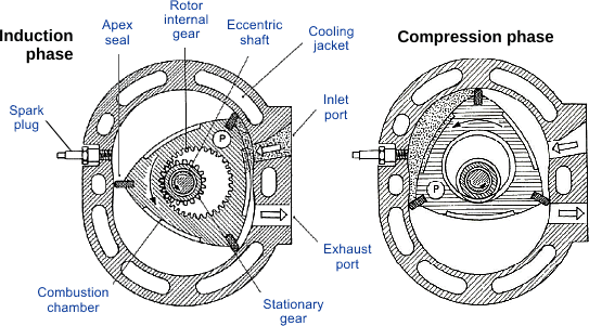
The Wankel engine, Figure 1, uses a wide triangular disc having rounded flanks. A recess in the middle of the side of each flank represents the combustion chamber. This triangular rotor is driven by an eccentric drive around which the rotor orbits. The rotor moves in an orbital fashion inside a housing whose epitrochoid shape resembles the figure eight. At each apex of the triangular rotor, a sliding seal mechanism is placed to reduce gas leakage between the two chambers on either side of the seal during the combustion phases. The combustion cycle is very similar to that of the reciprocating piston cycle. However, the rotating action of the triangular rotor/disc completes all phases of the combustion cycle without excessive unbalance forces experienced in the reciprocating engine.
(Courtesy of Heinz Heisler)
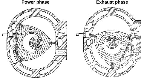
Figure 1, left, shows the induction phase of the rotary engine where the charge is drawn into the engine through the intake port as the rotor moves in a counterclockwise direction. The preceding charge is being compressed while the volume of the space between the flank of the rotor and the engine housing decreases. The seal at apex P is responsible for preventing leakage from the charge under compression to the freshly inducted charge side of the rotor. At the proper time, the spark plug initiates combustion while the rotor continues its counterclockwise rotation. The compression phase of the combustion cycle is shown on the right diagram in Figure 1. Both the expansion and exhaust phases of the combustion cycle are represented schematically in Figure 2. The Wankel engine delivers three power pulses per revolution of the rotor and the output shaft turns three times for each revolution of the rotor giving one power pulse per revolution of the output shaft.
(Courtesy of Heinz Heisler)
It should be noted that with Wankel’s idea of a rotating housing and rotor, both components would spin on their own axis and could be completely balanced to achieve very high rpm—up to 17,000 rpm reportedly. While Paschke’s development of a stationary housing led to a simpler design that could be more easily manufactured, the oscillation of the rotor must be counterbalanced and speeds maximum engine speeds were lower.
The Wankel engine has faced a number of technical challenges that have proven to be problematic at times. The most severe of these problems was finding a suitable material for the apex seal which can experience excessive wear resulting from moving across the sharp edges of the ports. Another serious problem was engine housing distortion due to a small area of the engine being cooled by the incoming charge and leaving the rest of the engine at a higher temperature. At excessive temperature differentials, the housing distortion affected oil consumption and cooling heat loss. Another major limitation of this engine was its low compression ratio, limited by the rotor geometric eccentricity. This problem was compounded by the apex seals that prevented high compression, leading eventually to low thermal efficiencies. The combustion chamber design also has high heat transfer characteristics and poor emissions performance due to the relatively large surface area-to-volume ratio and large crevice volumes. However, the engine is compact, simple, and capable of achieving relatively high speeds and high engine outputs with very little vibration.
While oil-cooled rotors are common in Wankel engines, compressed air is also used, Figure 3. In one such example by UAV Engines, the self-pressurized air-rotor cooling system (SPARCS), a small engine driven centrifugal fan circulates air/blowby gases through the rotor and then through an air/water heat exchanger for subsequent rejection. The circulating air is pressurized to the average pressure in the engine working chambers via a small two-way leakage of gases past the rotor side seals. At wide-open throttle, the cooling system can be pressurized to about 0.5 or 0.6 MPa that improves heat transfer. The SPARCS air-cooled rotor is claimed to eliminate the loss of wet oil particles out of the sealed system and lower friction than for an oil-cooled rotor (OCR). Friction is reduced because there is no oil scraper ring friction, no oil ‘cocktail shaker’ losses, rolling-element bearings, no oil pump to drive and a smaller rotor size that reduces gas seal friction [5323][5324][5325][5326].
![[photo]](images/engine/alternatives/uav_rotary.webp)
(Source: SAE International [5326])
In the 1960s and 1970s companies including Curtiss-Wright, automakers that included Mazda and GM, and several motorcycle manufacturers purchased Wankel production rights from patent owner Audi NSU. While the 1964 NSU Spider was the first production automobile to use a Wankel engine, Mazda can be credited with having the most successful application of the rotary engine. Mazda sold about 1.8 million vehicles equipped with a rotary engine starting with the 1967 Cosmo 110S and continuing until 2012 in the RX-8. Until 2017, the engine was reported to be produced in small volumes for some racing applications. Since 2013, Mazda continued to develop the engine and included it in some product plans. For example, in 2020, Mazda announced a SKYACTIV-R rotary engine for the Mazda RX-VISION rotary sports car concept. In 2023, Mazda started mass production of the European model of the MAZDA MX-30 e-SKYACTIV R-EV that uses a rotary engine as a range extender. The newly developed single-rotor 830 cm3 engine produces 55 kW at 4,700 rpm and is packaged with a generator and a 125 kW electric motor in the engine bay, Figure 4. In 2024, Mazda announced that it had reinstated the ‘RE Development Group’ to further evolve the rotary engine for generator applications and to carry out development work related to emissions compliance in major markets and the application of carbon-neutral fuels [6418].
(Source: Mazda)
While variable valve timing is difficult to apply to a Wankel engine, adding a second intake port controlled by a throttle valve is one option to achieve a similar effect. The second port can be opened to prolong the intake stroke and allow more air into the engine during high power demand but closed under low power to maintain low-speed efficiency. When the rotary engine is coupled to an electric machine as it is in Mazda’s MX-30 application, the electric machine can apply either positive or negative torque to the rotary engine's output shaft during the intake stroke that momentarily speeds up or slows down the rotor to further optimize the intake charge entry into the combustion chamber. If the rotary engine is only used to generate electricity, the speed variations would not be transmitted to the wheels [6417].
For motorcycle applications, Suzuki’s RE-5, produced from 1974-76, was one example of a commercially produced motorcycle with a rotary engine. Other motorcycle manufacturers that tested the concept included Hercules/DKW, Kawasaki, Yamaha and Norton [5327].
Wankel engines are commonly used in unmanned aerial vehicles (UAVs). In 2021, one manufacturer offered several rotary engine options rated between 35 and 120 hp [5328].
A compression ignition diesel version of the Wankel was attempted in the 1960s and 1970s by several manufacturers including a joint venture of Daimler-Benz, MAN, Krupp and KHD (the “Diesel-Ring”), Rolls-Royce and Felix Wankel himself. The shape of the rotor made it difficult to achieve an optimal compression ignition combustion chamber shape and a high enough compression ratio for ignition. External compression via a supercharger was required and led to high parasitic losses and increased weight. While some Wankel engines for UAV applications can operate with diesel fuel, these are typically spark ignition engines that burn a pre-mixed charge of diesel fuel and air and not compression ignition engines [5329]. The ability to run on diesel-type fuels is important for some military operations using a single fuel for a wide range of applications.
For hydrogen, the rotary engine has the advantage that the intake and combustion processes occur in different locations and preignition of hydrogen can more easily be avoided than in piston engines. Intake occurs at a relatively cool part of the housing without hot spots. Hydrogen fueled rotary engine research has been carried out by Mazda and others [5330][5331][5332]. Hydrogen fueled Wankel engines as range extenders for electric vehicle applications ranging from urban taxis and small cargo vans to large trucks are an option being considered [5326].
###