DieselNet Technology Guide » Combustion Systems
DieselNet | Copyright © ECOpoint Inc. | Revision 2026.11
This is a preview of the paper, limited to some initial content. Full access requires DieselNet subscription.
Please log in to view the complete version of this paper.
Variable compression ratio offers a number of benefits for diesel and gasoline engines. While the concept has been studied for many years [3537][3538][3539][3540][1942], the added cost and complexity have been difficult to justify for many applications. In modern applications, high volume production has been limited to Nissan’s Multi-Link mechanism for the 2 L I4 VC-Turbo for the Infinity and the 1.6L three-cylinder engine for the Rogue SUV. It is also available as an option in some low-speed marine engines. Developments that have provided a simpler mechanism through the use of variable length connecting rods could make this a viable option for a range of other applications including diesel engines.
A variety of mechanisms have been considered for VCR implementation. These include cranktrain and multi-link systems, connecting rod systems, crankshaft modulated eccentricity, auxiliary pistons mounted in the cylinder head, movement of the cylinder block relative to the crankshaft and hydraulic and spring mounted piston mechanisms. These options are discussed in detail by others [6881].
Efforts to develop VCR for modern applications have focused on either two-step systems where a low or a high compression ratio can be selected or continuously variable systems where any compression ratio between a low and high value can be selected.
Two-step systems include AVL’s and FEV’s variable length connecting rod. Continuously variable systems can be implemented through a variety of mechanisms including:
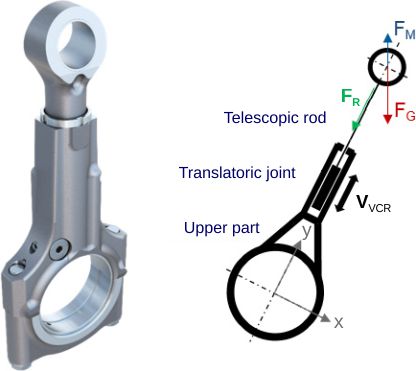
AVL’s two step variable compression ratio system uses a telescopic connecting rod, Figure 1. Actuation is by gas or mass forces. Inertia force FM and gas force FG are used to lengthen and shorten the connecting rod. The translatoric joint shortens the connecting rod when the resultant shaft force FR is toward the center of the crankshaft (FG > FM) and extends the connecting rod when it is in the opposite direction (FG < FM). Limit stops define the minimum and maximum connecting rod length. To “hold” one of the two positions, oil is transferred into the volumes below or above the translatoric joint. A control system signals when a change in connecting rod length is required [3518][3544].
###