(Source: Mitsubishi Heavy Industries)
DieselNet Technology Guide » Carbon Capture and Storage
DieselNet | Copyright © ECOpoint Inc. | Revision 2025.10
This is a preview of the paper, limited to some initial content. Full access requires DieselNet subscription.
Please log in to view the complete version of this paper.
The idea of using Carbon Capture and Storage CCS to reduce CO2 emissions from marine vessels, Onboard Carbon Capture and Storage (OCCS), is commonly discussed as an option to meet the IMO greenhouse gas reduction objectives such as the 2030 goal of a 40% reduction in carbon intensity. Other options for these objectives include low carbon fuels, vessel efficiency improvements and operational efficiency improvements.
Most marine OCCS systems are based on amine-based absorption processes. It has been demonstrated that the application of amine-based technologies to ships is technically feasible. However, the outlook from a cost perspective varies from optimistic [5959] to pessimistic [5957][5958].
The more optimistic outlooks either neglect to fully account for the total system costs or use simplified costing assumptions. While some marine vessels could use CCS to effectively reduce CO2 emissions, further development to limit energy consumption and costs and the development of a post-capture handling infrastructure to utilize or sequester captured emissions is required before carbon capture can be considered a viable option to reduce greenhouse gas emissions from a wider range of marine vessels.
Marine vessels typically employ two-stroke low- or four-stroke medium-speed engines for propulsion and several four-stroke generator sets for auxiliary power. Some may also employ a boiler that utilizes waste exhaust heat or that burns additional fuel to generate steam. All this combustion equipment contributes to carbon dioxide emissions from the ship, and a carbon capture system should be designed to handle either their collective exhaust gas or a portion thereof. The chemical absorption process using amine is considered mature for shore-based applications and is being developed for use on ships [5957][5958][5959][5960].
Chemical absorption using an amine solvent requires energy input in the form of heat and electricity that can impose a fuel consumption penalty and additional CO2 emissions that must be captured.
Figure 1 shows an amine-based system that could be used to capture carbon in marine vessels [5957]. Exhaust cleaning to remove sulfur and NOx can also be required.
HTF = Heat transfer fluid, such as steam from a fuel-fired boiler.
(Source: Oil and Gas Climate Initiative [5957])
First, water quenching is used to lower the temperature of the exhaust gas to approximately 40°C, a temperature at which carbon dioxide is readily absorbed in the next stage by an aqueous solution of monoethanolamine (MEA), a first-generation amine solution widely used in carbon capture applications. In this system, a blower compensates for the pressure drop induced by the overall system to avoid negative performance impacts on the two-stroke propulsion engine. The cooled exhaust gas then enters the absorber column where it is exposed to the amine sorbent and carbon dioxide is absorbed into the solution. Most of the volatile amine carried out of the absorber is removed from the exhaust gas by the water wash and returned to the column.
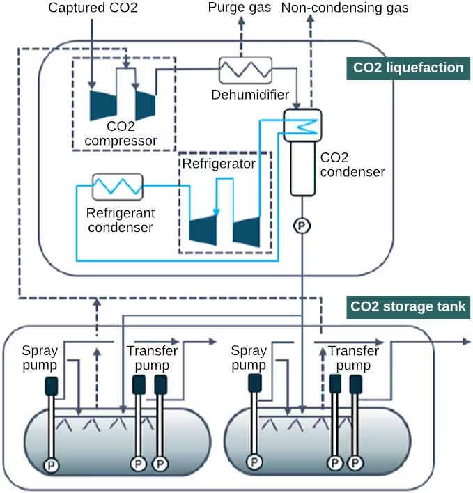
The carbon dioxide-enriched amine is then pumped from the bottom of the absorber and sent through a heat exchanger to scavenge energy from the carbon dioxide-lean amine returning from the stripper. At the bottom of the stripper the temperature of the amine solution is increased to about 120°C at 2 bar. A reboiler raises part of the amine solution to the boiling point to introduce sufficient vapor to strip the carbon dioxide from the solvent. Concentrated carbon dioxide and water vapor exit the top of the stripper and are then cooled and flashed to remove residual water and amine, which is returned to the main loop. The almost pure gaseous carbon dioxide is then sent to a final quench station where remaining impurities are removed and finally to a liquefaction system, Figure 2, where it is compressed, liquefied and pumped into holding tanks at a pressure of 16 to 20 bar [5958][5957].
(Source: Mitsubishi Heavy Industries)
Exhaust is supplied to the capture system from the SOx scrubber. This is where SOx concentration is lowest. SOx is preferentially absorbed by the amine and forms heat stable salts which deactivate the amine group and prevent it from absorbing CO2. As a result, periodic replacement of the solvent is necessary. Figure 3 shows the theoretical effect of different SOx concentrations, as SO2, on solvent deactivation assuming that all SOx species are absorbed into the liquid phase [6313].
NO2 should also be removed prior to CO2 capture as it oxidizes amines and degrades their performance. Solvent losses due to degradation as high as 3.5-4 kg MEA/tCO2 have been observed when amines were exposed to NO2 emissions from 100 to 400 mg/Nm3. With amine solvents, NOx emissions from the engine may need to be considerably lower than the existing IMO limits to minimize this effect. In land-based CO2 capture systems, amines are typically exposed to 2-5 mg/Nm3 NO2 [6591].
The major energy consumers in the process are the heat required in the reboiler and the electricity required for the liquefaction plant’s compressor and chiller. Depending on the vessel’s needs, some of the heat required for the reboiler could be supplied using waste heat from the engine. Any additional heat would be supplied by a fuel-fired boiler. In cases where the heat consumption of the capture system is to be met with waste heat, the amount of waste heat available will limit the CO2 capture rate. The electricity consumption, however, will be an additional load on the auxiliary engines and will result in additional fuel consumption. Engines burning LNG may be able to save on liquefaction costs by using CO2 from the stripper to vaporize LNG supplied to the engine [5961][5965].
The availability of waste heat depends on several factors. On-board four-stroke engines typically have exhaust temperatures over 300°C which makes them excellent candidates for waste heat recovery. On the other hand, the exhaust temperature from two-stroke engines is often 200-250°C and waste heat recovery is more challenging. For vessels burning HFO, waste heat is often used to maintain low fuel viscosity and little waste heat may be available for the carbon capture system [6592]. In some cases, it may be feasible to tune the engine(s) to increase exhaust temperature to increase waste heat availability with only a small engine efficiency penalty but a significant increase in the amount of CO2 that can be captured without having to resort to heat from a fuel-fired boiler [6593].
For LNG fueled vessels, cold recovery for CO2 liquefaction from LNG vaporization can depend on the amount of boil-off from the LNG tank relative to the vessel’s fuel consumption. For vessels with a relatively small LNG tank, this is feasible but for vessels with very large LNG tanks, boiloff is typically too high to recover any cold from LNG vaporization. However, with large amounts of boil-off, the cold available in the already vaporized LNG could be used to provide some benefit [6592][6595].
The energy requirement of the process is dependent on the solvent used in the absorption process. Monoethanolamine (MEA) requires around 3.5 GJ/tCO2 captured. Solvents requiring less energy have been identified such as Siemen’s amino acid salt which requires 2.7 GJ/tCO2 and an amine mixture by Mitsubishi that requires less than 3 GJ/tCO2 [5965]. Other solvents are also under development [5962].
Energy requirements for the carbon capture system on-board ships can be higher than land-based applications. As discussed elsewhere, the relatively low CO2 concentration and low temperature of marine two-stroke engine exhaust can contribute to this. Compromises in equipment design to allow it to be installed on-board can also contribute. In one example, a height restriction imposed on the capture equipment led to a reboiler heat demand of 4.62 GJ/tCO2, which was considerably higher than for gas-fired power plants with a similar CO2 concentration in the flue gas [6594].
In addition to the increased fuel consumption, loss of cargo capacity and the structural design of the vessel need to be considered. The need for onshore infrastructure to offload and dispose of CO2 and suitable market mechanisms would be required for carbon capture to be a viable option.
###