DieselNet | Copyright © ECOpoint Inc. | Revision 2026.06
This is a preview of the paper, limited to some initial content. Full access requires DieselNet subscription.
Please log in to view the complete version of this paper.
Carbon capture and storage (CCS) or carbon capture utilization and storage (CCUS) technologies involve the capture of CO2, primarily from large point sources like power generation. Application to more dispersed sources such as ships and vehicles as well as direct air capture have also been proposed. The captured CO2 could be utilized in a range of applications or else injected into deep geological formations such as depleted oil and gas reservoirs or saline aquifers. Some climate policy centers consider a wide-scale deployment of CCS/CCUS technologies to be necessary to achieve ‘net zero’ GHG emission goals and to decarbonize sectors with hard-to-abate emissions [5968].
Carbon capture technologies still require much work to be deployed on a wider scale. As CCS processes require high energy input, they tend to have a significant negative impact on the efficiency and the economics of the associated industrial process. Experience shows that CCS technologies also present a range of technical and scalability challenges [5753]. In the United States, CCS demonstration projects resulted in varying levels of success, despite sizable government subsidies [5969].
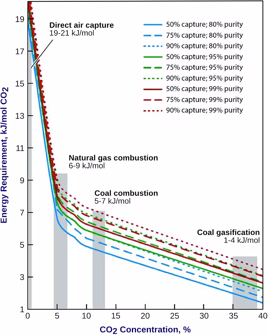
To separate a compound such as CO2 from a gas stream containing other compounds, the second law of thermodynamics requires that work be carried out to perform the separation. The theoretical minimum amount of work of separation that is required can be directly determined from the Gibbs free energy of the mixture from which CO2 is to be separated. The lower the concentration of CO2 in the mixture, the higher the work of separation. The minimum work of separation also increases as the purity of the captured CO2 increases, Figure 1 [6536].
Additionally, the efficiency of a given separation process (i.e., the ratio of the theoretical minimum work of separation to the real work of separation) decreases with increasing dilution of CO2 concentration because the amount of unwanted or inert gas (mostly nitrogen) that needs to be processed increases [6537] [6538]. However, different processes can have significantly different second law efficiencies. Some of this difficulty can be overcome by using processes that are more efficient for separation of lower concentration CO2 mixtures. The second law efficiency of CO2 separation from several industrial processes where the CO2 concentration prior to separation ranges from 3.6% to 90% ranges from 11% to 25% [6539]. For capture of CO2 from the ambient air (direct air capture) where the CO2 concentration is about 400 ppm, the second law efficiency for many processes ranges from 5-10% [6540].
The work of separation only accounts for the energy required to separate CO2 from a gas stream. Additional energy will be required to move the source gas through the separation plant and prepare the separated CO2 for transport through compression and/or liquefaction.
###